Assembly
10 February 2018 · Filed in TutorialAssebly
Register
To speed up the processor operations, the processor includes some internal memory storage locations, called registers.
There are ten 32-bit and six 16-bit processor registers in IA-32 architecture.
The registers are grouped into three categories −
General registers, Control registers, and Segment registers. The general registers are further divided into the following groups −
Data registers, Pointer registers, and Index registers.
Data Registers
System calls are APIs for the interface between the user space and the kernel space.
Nibbles
A nibble is a collection of four bits
Bytes
Bits 0..3 comprise the low order nibble, bits 4..7 form the high order nibble. Since a byte contains exactly two nibbles, byte values require two hexadecimal digits.
Since a byte contains eight bits, it can represent 28, or 256, different values. Generally, we’ll use a byte to represent numeric values in the range 0..255, signed numbers in the range -128..+127
Words
A word is a group of 16 bits.
Double Words
A double word is exactly what its name implies, a pair of words.
Signed and Unsigned Numbers
with n bits we can represent the signed values in the range -2n-1 to +2n-1-1.
00000000	+0	0
00000001	1	1
⋮	⋮	⋮
01111101	125	125
01111110	126	126
01111111	127	127
10000000	−127	128
10000001	−126	129
10000010	−125	130
⋮	⋮	⋮
11111101	−2	253
11111110	−1	254
11111111	−0	255
1) Invert all the bits in the number 2) Add one to the inverted result
0000 0101 Five (in binary). 1111 1010 Invert all the bits. 1111 1011 Add one to obtain result.
Shifts and Rotates
Another set of logical operations which apply to bit strings are the shift and rotate operations. These two categories can be further broken down into left shifts, left rotates, right shifts, and right rotates.
shifting it left multiplies it by two.
If you shift a binary value to the left three times, you multiply it by eight (222) If you perform n right shifts, you will divide that number by 2n
The ASCII Character Set
Von Neumann architecture (VNA)
Buses
The system bus
The system bus connects the various components of a VNA machine
The Data Bus
The Address Bus
The Control Bus
The CPU sends data to memory and receives data from memory on the data bus. This prompts the question, “Is it sending or receiving?” There are two lines on the control bus, read and write, which specify the direction of data flow
The 80x86 family deals with this problem by storing the L.O. byte of a word at the address specified and the H.O. byte at the next location
CPU Registers
AX –The accumulator register BX –The base address register CX –The count register DX –The data register
Besides the above registers, which are visible to the programmer, the x86 processors also have an instruction pointer register which contains the address of the next instruction to execute. There is also a flags register that holds the result of a comparison. The flags register remembers if one value was less than, equal to, or greater than another value.
Because registers are on-chip and handled specially by the CPU, they are much faster than memory
Accessing a memory location requires one or more clock cycles. Accessing data in a register usually takes zero clock cycles
The Arithmetic & Logical Unit
For example, if you want to add the value five to the AX register, the CPU: • Copies the value from AX into the ALU, • Sends the value five to the ALU, • Instructs the ALU to add these two values together, • Moves the result back into the AX register.
The Bus Interface Unit
The bus interface unit (BIU) is responsible for controlling the address and data busses when accessing main memory. If a cache is present on the CPU chip then the BIU is also responsible for accessing data in the cache.
The Control Unit and Instruction Sets
CBA Instruction 000 move 001 add 010 subtract 011 multiply 100 divide 101 and 110 or 111 xor DD SS DD -or- SS Register 00 AX 01 BX 10 CX 11 DX
log2(n)
The move instruction would move data from the source register to the destination register the add instruction would add the value of the source register to the destination register, etc.
The x86 Instruction Set
The instructions are mov (two forms), add, sub, cmp, and, or, not, je, jne, jb, jbe, ja, jae, jmp, brk, iret, halt, get, and put.
mov reg, reg/memory/constant mov memory, reg
The arithmetic and logical instructions
add reg, reg/memory/constant
sub reg, reg/memory/constant
cmp reg, reg/memory/constant
and reg, reg/memory/constant
or reg, reg/memory/constant
not reg/memory
The add instruction adds the value of the second operand to the first (register) operand, leaving the sum in the first operand. The sub instruction subtracts the value of the second operand from the first, leaving the difference in the first operand. The cmp instruction compares the first operand against the second and saves the result of this comparison for use with one of the conditional jump instructions (described in a moment). The and and or instructions compute the corresponding bitwise logical operation on the two operands and store the result into the first operand. The not instruction inverts the bits in the single memory or register operand.
The control transfer instructions
ja dest – Jump if above jae dest – Jump if above or equal jb dest – Jump if below jbe dest – Jump if below or equal je dest – Jump if equal jne dest – Jump if not equal jmp dest – Unconditional jump iret – Return from an interrupt
The first six instructions in this class let you check the result of the previous cmp instruction for greater than, greater or equal, less than, less or equal, equality, or inequality
Addressing Modes on the x86
The x86 processors support the register addressing mode10, the immediate addressing mode, the indirect addressing mode, the indexed addressing mode, and the direct addressing mode.
mov ax, [1000] mov ax, [bx] mov ax, [1000+bx]
The first instruction above uses the direct addressing mode to load ax with the 16 bit value stored in memory starting at location 1000 hex. The mov ax, [bx] instruction loads ax from the memory location specified by the contents of the bx register. This is an indirect addressing mode
mov bx, 1000 mov ax, [bx]
are equivalent to the single instruction:
mov ax, [1000]
Of course, the second sequence is preferable
The last memory addressing mode is the indexed addressing mode. An example of this memory addressing mode is mov ax, [1000+bx]
3.3.7 Encoding x86 Instructions
i i i r r m m m
i i i
000 = special
001 = or
010 = and
011 = cmp
100 = sub
101 = add
110 = mov reg, mem/reg/const
111 = mov mem, reg

r r
00 = AX
01 = BX
10 = CX
11 = DX

mmm
0 0 0 = AX
0 0 1 = BX
0 1 0 = CX
0 1 1 = DX
1 0 0 = [BX]
1 0 1 = [xxxx+BX]
1 1 0 = [xxxx]
1 1 1 = constant
0 0 0 i i m m m

i i
00 = zero operand instructions
01 = jump instructions
10 = not
11 = illegal (reserved)

mmm (if ii = 10)
000 = AX
001 = BX
010 = CX
011 = DX
100 = [BX]
101 = [ xxxx+BX]
110 = [ xxxx]
111 = constant
For example, to encode the mov ax, bx instruction you would select iii=110 (mov reg, reg), rr=00 (ax), and mmm=001 (bx). This produces the one-byte instruction 11000001 or 0C0h.
0 0 0 0 0 i i i
i i i
000 = illegal
001 = illegal
010 = illegal
011 = brk
100 = iret
101 = halt
110 = get
111 = put
0 0 0 0 1 i i i
mmm (if ii = 10)
000 = j e
001 = jne
010 = j b
011 = jbe
100 = j a
101 = jae
110 = jmp
111 = illegal
jxx address The jmp instruction copies the 16-bit immediate value (address) following the opcode into the IP register. Therefore, the CPU will fetch the next instruction from this target address; effectively, the program “jumps” from the point of the jmp instruction to the instruction at the target address.
Three of these instructions are illegal instruction opcodes. The brk (break) instruction pauses the CPU until the user manually restarts it. This is useful for pausing a program during execution to observe results. The iret (interrupt return) instruction returns control from an interrupt service routine. We will discuss interrupt service routines later. The halt program terminates program execution. The get instruction reads a hexadecimal value from the user and returns this value in the ax register; the put instruction outputs the value in the ax register.
Step-by-Step Instruction Execution
the mov reg, reg/memory/constant instruction: • Fetch the instruction byte from memory. • Update the ip register to point at the next byte. • Decode the instruction to see what it does. • If required, fetch a 16-bit instruction operand from memory. • If required, update ip to point beyond the operand. • Compute the address of the operand, if required (i.e., bx+xxxx) . • Fetch the operand. • Store the fetched value into the destination register
section.data text db “Hello, World!”, 10
section .text global _start _start: mov rax, 1 mov rdi, 1 mov rsi, text mov rdx, 14 syscall
mov rax, 60
mov rdi, 0
syscall
text db “Hello, World!”, 10
db define bite 10 is new line \n
text name of memmory address
• A bit is a single binary digit, 0 or 1. • A byte is 8 bits side by side. • A word is 2 bytes side by side. • A double word is 2 words side by side. • A quad word is 2 double words side by side.
The Linux kernel was entirely separate from the user interface, and it was protected from damage due to malfunctioning programs elsewhere in the system. System memory was tagged as either kernel space or user space, and nothing running in user space could write to (nor generally read from) anything stored in kernel space. Communication between kernel space and user space was handled through strictly controlled system calls
Direct access to physical hardware, including memory, video, and periph- erals, was limited to software running in kernel space. Programs wishing to make use of system peripherals could only get access through kernel-mode device drivers.
Memory model
The oldest and now ancient memory model is called the real mode flat model
The newest memory model is called protected mode flat model, and it’s the memory model behind modern operating systems such as Windows 2000/XP/Vista/7 and Linux.
Real mode flat model is very much like protected mode flat model in miniature.
NAME VALUE IN DECIMAL VALUE IN HEX Byte 1 01H Word 2 02H Double word 4 04 H Quad word 8 08H Ten byte 10 OAH Paragraph 16 10H Page 256 100H Segment 65,536 10000H
The segment registers exist only to hold segment addresses.
The segment registers have names that reflect their general functions: CS, DS, SS, ES, FS, and GS. FS and GS exist only in the 386 and later Intel x86 CPUs—but are still 16 bits in size. All segment registers are 16 bits in size, irrespective of the CPU. This is true even of the 32-bit CPUs.
• CS stands for code segment. Machine instructions exist at some offset into a code segment. The segment address of the code segment of the currently executing instruction is contained in CS. DS stands for data segment. Variables and other data exist at some offset into a data segment. There may be many data segments, but the CPU may only use one at a time, by placing the segment address of that segment in register DS. SS stands for stack segment. The stack is a very important component of the CPU used for temporary storage of data and addresses. I explain how the stack works a little later; for now simply understand that, like everything else within real mode’s megabyte of memory, the stack has a segment address, which is contained in SS. ES stands for extra segment. The extra segment is exactly that: a spare segment that may be used for specifying a location in memory. FS and GS are clones of ES. They are both additional segments with no specific job or specialty. Their names come from the fact that they were created after ES (think, E, F, G). Don’t forget that they exist only in the 386 and later x86 CPUs!
these general-purpose registers are used to hold the offset addresses that must be paired with segment addresses to pin down a single location in memory.
The ‘‘bitness’’ of the world is almost entirely defined by the width of the x86 CPU registers.
Adding a room to your house doesn’t make it two houses—just one bigger house.
There are eight 16-bit general-purpose registers: AX, BX, CX, DX, BP, SI, DI, and SP. They are all 16 bits in size, and you can place any value in them that may be expressed in 16 bits or fewer.
When Intel expanded the x86 architecture to 32 bits in 1986, it doubled the size of all eight registers and gave them new names by prefixing an E in front of each register name, resulting in EAX, EBX, ECX, EDX, EBP, ESI, EDI, and ESP.
EAX, EBX, ECX, and EDX, but there’s an additional twist: the low 16 bits are themselves divided into two 8-bit halves, so what we have are register names on not two but three levels
The 16-bit registers AX, BX, CX, and DX are present as the lower 16-bit portions of EAX, EBX, ECX, and EDX; but AX, BX, CX, and DX are themselves divided into 8-bit halves, and assemblers recognize special names for the two halves. The A, B, C, and D are retained, but instead of the X, a half is specified with an H (for high half) or an L (for low half). Each register half is one byte (8 bits) in size.
BX there is BH and BL
The Instruction Pointers
usually called IP or, in 32-bit protected mode, EIP
It can do only one thing: it contains the offset address of the next machine instruction to be executed in the current code segment.
A code segment is an area of memory where machine instructions are stored.
The current code segment is that code segment whose segment address is currently stored in code segment register CS.
Together, CS and IP contain the full address of the next machine instruction to be executed.
The nature of this address depends on what CPU you’re using, and the programming model for which you’re using it
The Flags Register
The Three Major Assembly Programming Models
Real Mode Flat Model
CS always points to the current code segment, and the next instruction to be executed is pointed to by the IP register
You can destroy portions of the operating system by careless use of segment registers, which will cause the operating system to crash and take your program with it. This is the danger that prompted Intel to build new features into its 80386 and later CPUs to support a ‘‘protected’’ mode. In protected mode, application programs (that is, the programs that you write, as opposed to the operating system or device drivers) cannot destroy the operating system or other application programs that happen to be running elsewhere in memory via multitasking. That’s what the protected means.
The 64-bit versions of the registers are renamed beginning with an R: EAX becomes RAX, EBX becomes RBX, and so on.
Linux comes with its own linker, called ld.
Everything is a file.
When you read from a file, you are accepting data from an endpoint. The path that the data takes between files may be entirely within a single computer, or it may be between computers along a network of some kind. Data may be processed and changed along the path, or it may simply move from one endpoint to another without modification. No matter. Everything is a file, and all files are treated more or less identically by Unix’s internal file machinery
Your keyboard is a file: it’s an endpoint that generates data and sends it somewhere. Your display is a file: it’s an endpoint that receives data from somewhere and puts it where you can see it. Unix files do not have to be text files. Binary files (like the executables created by NASM and the linker) are handled the same way.
FILE C IDENTIFIER FILE DESCRIPTOR DEFAULTS TO Standard Input stdin 0 Keyboard Standard Output stdout 1 Display Standard Error stderr 2 Display
but it’s good to know that the power is there as your programming skills improve and you take on more ambitious projects.
By convention in assembly language, the first (leftmost) operand belonging to a machine instruction is the destination operand. The second operand from the left is the source operand.
Three different flavors of data may be used as operands: memory data, register data, and immediate data.
you can move an immediate value to memory, or a memory value to a register, or some other similar combination, but you can’t move a memory value directly to another memory value. This is just an inherent limitation of the current generation of x86 CPUs, and we have to live with it, inconvenient as it is at times.
to move the word in memory at the address contained in EBX into register EAX, you would use the following instruction: mov eax,[ebx]
EatMsg: db “Eat at Joe’s!” mov ecx,EatMsg
If you’ve had any exposure to high-level languages like Pascal, your first instinct might be to assume that whatever data is stored in EatMsg will be copied into ECX. Assembly doesn’t work that way. That MOV instruction actually copies the address of EatMsg, not what’s stored in (actually, at) EatMsg. In assembly language, variable names represent addresses, not data!
So how do you actually ‘‘get at’’ the data represented by a variable like EatMsg? Again, it’s done with square brackets: mov edx,[EatMsg]
EFlags as a whole is a single 32-bit register buried inside the CPU. It’s the 32-bit extended descendent of the 16-bit Flags register present in the 8086/8088 CPUs
• OF: The Overflow flag is set when the result of an arithmetic operation on a signed integer quantity becomes too large to fit in the operand it originally occupied. OF is generally used as the ‘‘carry flag’’ in signed arithmetic.
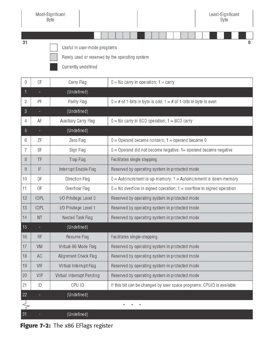
Several x86 machine instructions come in pairs. Simplest among those are INC and DEC,
Every executable program for Linux has to have a label _ s t a r t in it somewhere, irrespective of the language it’s written in: C, Pascal, assembly, no matter. If the Linux loader can’t find the label, it can’t load the program correctly. The g l o b a l specifier tells the linker to make the _ s t a r t label visible from outside the program’s borders.
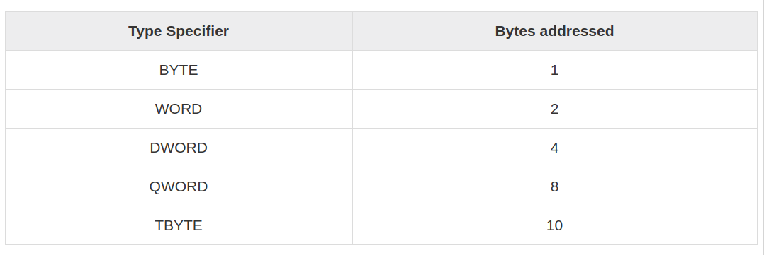
MyByte db 07h ; 8 bits in size MyWord dw 0FFFFh ; 16 bits in size MyDouble dd 0B8000000h ; 32 bits in size
Think of the DB directive as ‘‘Define Byte.’’ DB sets aside one byte of memory for data storage. Think of the DW directive as ‘‘Define Word.’’ DW sets aside one word (16 bits, or 2 bytes) of memory for data storage. Think of the DD directive as ‘‘Define Double.’’ DD sets aside a double word in memory for storage, typically for full 32-bit memory addresses.
TwoLineMsg: db “Eat at Joe’s…“,10,”…Ten million flies can’t ALL be wrong!”,10
What’s with the numeric literal 10 tucked into the previous example strings? In Linux text work, the end-of-line (EOL) character has the numeric value of 10. It indicates to the operating system where a line submitted for display to the Linux console ends.
You can concatenate such individual numbers within a string, but you must remember that, as with EOL, they will not appear as numbers. A string is a string of characters. A number appended to a string will be interpreted by most operating system routines as an ASCII character.
You can define string variables using DW or DD, but they’re handled a little differently than those defined using DB. Consider these variables: WordString: dw CQ 1
DoubleString: dd ‘Stop’ The DW directive defines a word-length variable, and a word (16 bits) may hold two 8-bit characters. Similarly, the DD directive defines a double word (32-bit) variable, which may hold four 8-bit characters.
A statement containing the directive EQU is called an equate. An equate is a way of associating a value with a label. Such a label is then treated very much like a named constant in Pascal. Any time the assembler encounters an equate during an assembly, it will swap in the equate’s value for its name. For example:
FieldWidth equ
The preceding tells the assembler that the label F i e l d w i d t h stands for the numeric value 10. Once that equate is defined, the following two machine instructions are exactly the same:
mov eax,10 mov eax,FieldWidth
EatLen: equ $-EatMsg
The assembly-time calculation is to take the location represented by the $ token (which, when the calculation is done, contains the location just past the end of the E a t M s g string) and subtract from it location of the beginning of the E a t M s g string. End - Beginning = Length
In the x86 architecture, the top of the stack is marked by a register called the stack pointer, with the formal name ESP. It’s a 32-bit register, and it holds the memory address of the last item pushed onto the stack.
the stack begins up at the ceiling, and as items are pushed onto the stack, the stack grows downward, toward low memory.
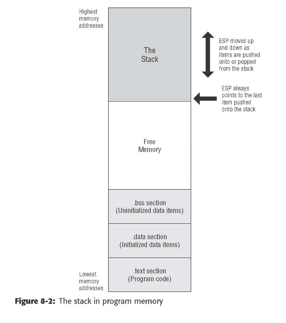
Push-y Instructions You can place data onto the stack in several ways, but the most straightforward way involves a group of five related machine instructions: PUSH, PUSHF, PUSHFD, PUSHA, and PUSHAD. All work similarly, and differ mostly in what they push onto the stack: PUSH pushes a 16-bit or 32-bit register or memory value that is specified by you in your source code.
• PUSHF pushes the 16-bit Flags register onto the stack. • PUSHFD pushes the full 32-bit EFlags register onto the stack. • PUSHA pushes all eight of the 16-bit general-purpose registers onto the stack. • PUSHAD pushes all eight of the 32-bit general-purpose registers onto the stack.


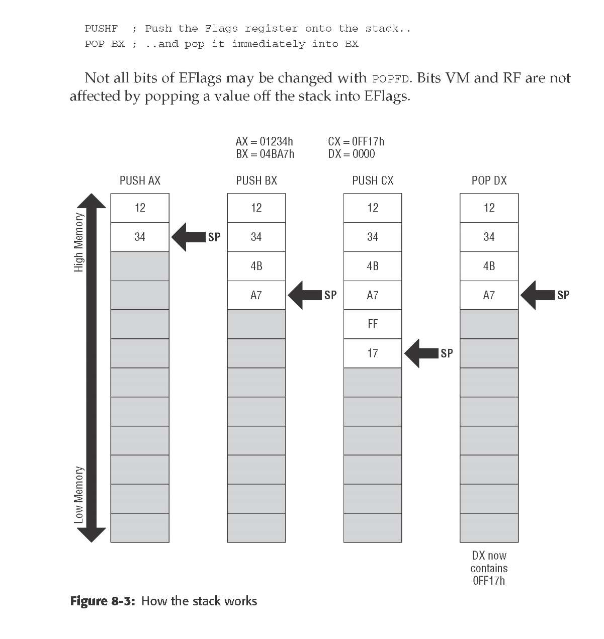
One excellent use of the stack allows the all-too-few registers to do multiple duty. If you need a register to temporarily hold some value to be operated on by the CPU and all the registers are in use, push one of the busy registers onto the stack. Its value will remain safe on the stack while you use the register for other things. When you’re finished using the register, pop its old value off the stack—and you’ve gained the advantages of an additional register without really having one
kernel services call gate
pooling
INT 00h - 0FFh 256 interrupts
The physical address is calculated from 2 parts. i) segment address. ii) offset address. The CS(code segment register) is used to address the code segment of the memory i.e a location in the memory where the code is stored. The IP(Instruction pointer) contains the offset within the code segment of the memory. Hence CS:IP is used to point to the location (i.e to calculate the physical address)of the code in the memory.
Since IP is 16 bit it means you can only have 64k instructions (2^16), which wasn’t much even in the 80s. So to expand the address space you have a second register which addresses 64k blocks. You could consider cs:ip together as one 32 bit register which is then capable of addressing 2^32 bytes…ie 4G which is what you get on a processor which uses 32 bit addresses. The 8086 was using 20 bits of addresses, so you could access 1M of memory.
INT 00h - 0FFh 256 interrupts
- Executes the INT instuction
- Interprets the INT instruction during the assembly time
- Moves the INT instruction to the Vector Table
- Vector Table occupies location 00 to 3FF of the program memory
- It contains the Code Segment(CS) and Instruction Pointer(IP) for each kind of interrupt
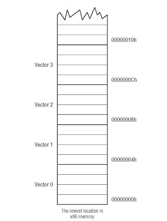
At the very start of x86 memory, down at segment 0, offset 0, is a special lookup table with 256 entries. Each entry is a complete memory address including segment and offset portions, for a total of 4 bytes per entry. The first 1,024 bytes of memory in any x86 machine are reserved for this table, and no other code or data may be placed there.
Each of the addresses in the table is called an interrupt vector. The table as a whole is called the interrupt vector table.

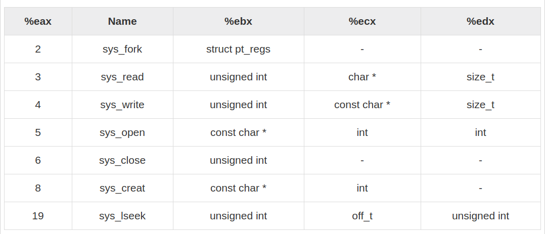
mov ecx,EatMsg mov edx,EatLen int 80H
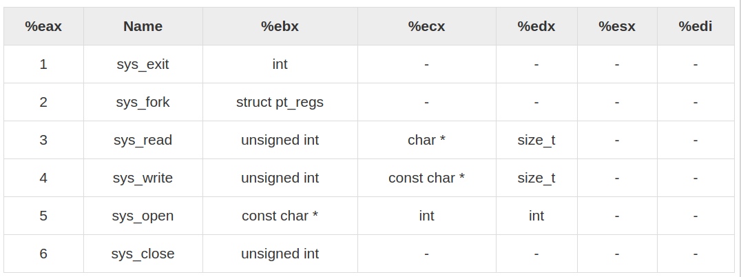
This sequence of instructions requests that Linux display a text string on the console. The first line sets up a vital piece of information: the number of the service that we’re requesting. In this case, it’s to sys_write, service number 4, which writes data to a Linux file. Remember that in Linux, just about everything is a file, and that includes the console. The second line tells Linux which file to write to: standard output. Every file must have a numeric file descriptor, and the first three (0,1, and 2) are standard and never change. The file descriptor for standard output is 1. The third line places the address of the string to be displayed in ECX. That’s how Linux knows what it is that you want to display. The dispatcher expects the address to be in ECX, but the address is simply where the string begins. Linux also needs to know the string’s length, and we place that value in register EDX.
mov eax,1 Specify Exit syscall mov ebx,0 Return a code of zero int 80H Make syscall the to terminate the program
Exiting this way is not just a nicety. Every program you write must exit by making a call to s y s _ e x i t through the kernel services dispatcher. If a program just ‘‘runs off the edge’’ it will in fact end, but Linux will hand up a segmentation fault and you’ll be none the wiser as to what happened.
Software Interrupts versus Hardware Interrupts
hardware interrupts are numbered, and for each interrupt number there is a slot reserved in the interrupt vector table. In this slot is the address of an interrupt service routine (ISR) that performs some action relevant to the device that tapped the CPU on the shoulder
The only real difference between hardware and software interrupts lies in the event that triggers the trip through the interrupt vector table. With a software interrupt, the triggering event is part of the software—that is, an INT instruction. With a hardware interrupt, the triggering event is an electrical signal applied to the CPU chip itself without any INT instruction taking a hand in the process. The CPU itself pushes the return address onto the stack when it recognizes the electrical pulse that triggers the interrupt; however, when the ISR is done, an IRET instruction sends execution home, just as it does for a software interrupt.
Write:	mov eax,4 		;Specify sys_write call
		mov ebx,1 		;Specify File Description 1 standad output
		mov ecx,Buff	;Pass address of the charecter to write
		mov edx,1		;Pass number of chars to write
		int 80H 		;Call sys_write...
EOF.
When you count bits, start with the bit on the right, and number them from 0.
SHL SHifts its operand Left, whereas SHR SHifts its operand Right.
0B76FH is as follows: 1011011101101111 SHL AX,1
0110111011011110
A 0 has been inserted at the right-hand end of the number, and the whole shebang has been bumped toward the left by one digit. The last bit shifted out of the left end of the binary number is bumped into a temporary bucket for bits called the Carry flag, generally abbreviated as CF.
ROL shifts all bits left and moves bit 7 to bit 0. What was 10110010 is now 01100101
nybble??
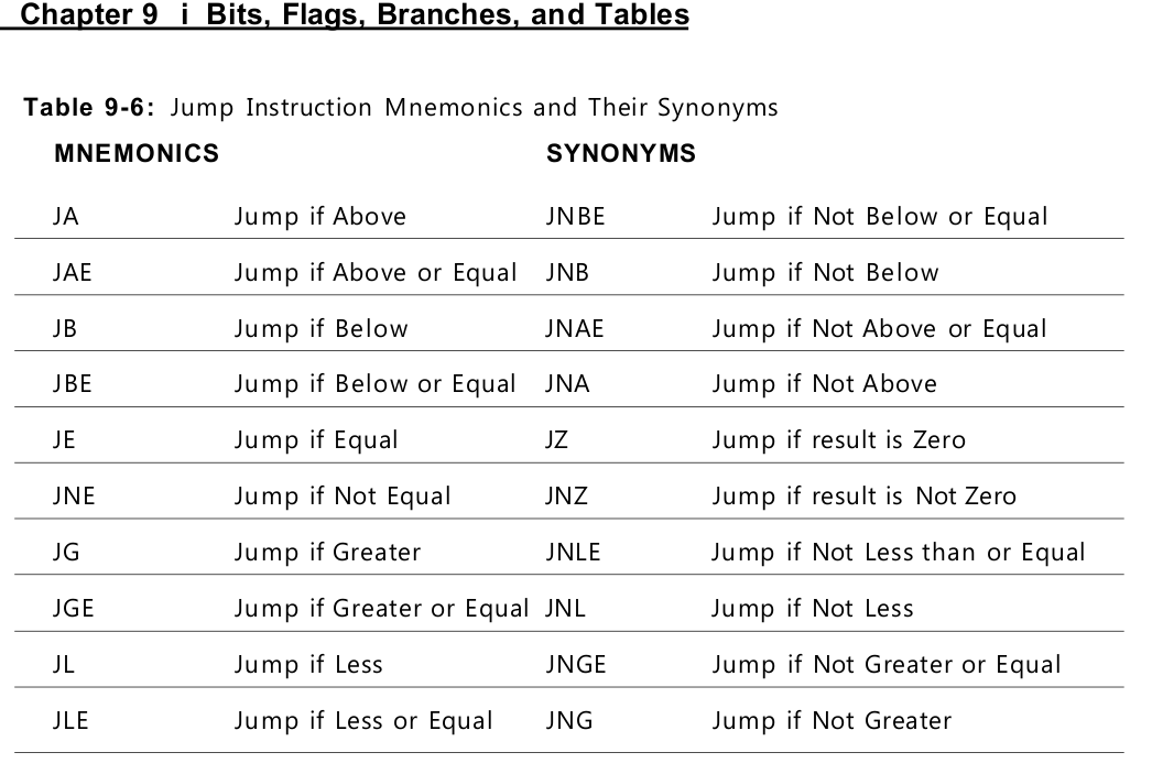
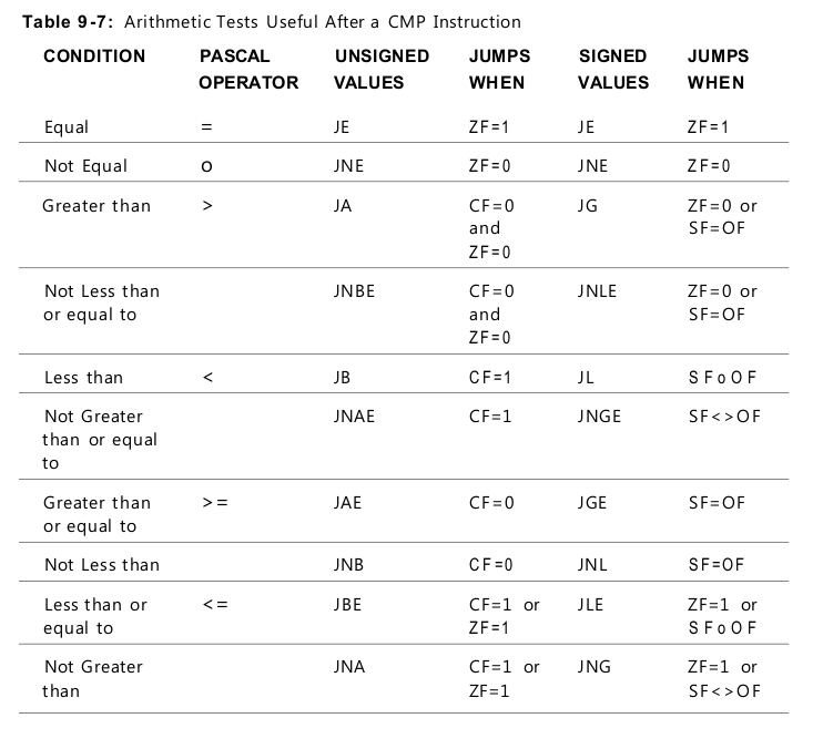
“Greater Than” Versus “Above”
To tell the signed jumps apart from the unsigned jumps, the mnemonics use two different expressions for the relationship between two values: • Signed values are thought of as being greater than or less than. For example, to test whether one signed operand is greater than another, you would use the JG (Jump if Greater) mnemonic after a CMP instruction. • Unsigned values are thought of as being above or below. For example, to tell whether one unsigned operand is greater than (above) another, you would use the JA (Jump if Above) mnemonic after a CMP instruction.
The three basic modes of addressing are −
Register addressing Immediate addressing Memory addressing
Register Addressing
In this addressing mode, a register contains the operand. Depending upon the instruction, the register may be the first operand, the second operand or both.
For example,
MOV DX, TAX_RATE   ; Register in first operand
MOV COUNT, CX	   ; Register in second operand
MOV EAX, EBX	   ; Both the operands are in registers
Immediate Addressing
An immediate operand has a constant value or an expression. When an instruction with two operands uses immediate addressing, the first operand may be a register or memory location, and the second operand is an immediate constant. The first operand defines the length of the data.
For example,
BYTE_VALUE  DB  150    ; A byte value is defined
WORD_VALUE  DW  300    ; A word value is defined
ADD  BYTE_VALUE, 65    ; An immediate operand 65 is added
MOV  AX, 45H           ; Immediate constant 45H is transferred to AX
BYTE_TABLE DB  14, 15, 22, 45      ; Tables of bytes
WORD_TABLE DW  134, 345, 564, 123  ; Tables of words
The following operations access data from the tables in the memory into registers −
MOV CL, BYTE_TABLE[2]	; Gets the 3rd element of the BYTE_TABLE
MOV CL, BYTE_TABLE + 2	; Gets the 3rd element of the BYTE_TABLE
MOV CX, WORD_TABLE[3]	; Gets the 4th element of the WORD_TABLE
MOV CX, WORD_TABLE + 3	; Gets the 4th element of the WORD_TABLE
Indirect Memory Addressing
MY_TABLE TIMES 10 DW 0  ; Allocates 10 words (2 bytes) each initialized to 0
MOV EBX, [MY_TABLE]     ; Effective Address of MY_TABLE in EBX
MOV [EBX], 110          ; MY_TABLE[0] = 110
ADD EBX, 2              ; EBX = EBX +2
MOV [EBX], 123          ; MY_TABLE[1] = 123



choice		DB	'y'
number		DW	12345
neg_number	DW	-12345
big_number	DQ	123456789
real_number1	DD	1.234
real_number2	DQ	123.456
Each byte of character is stored as its ASCII value in hexadecimal. Each decimal value is automatically converted to its 16-bit binary equivalent and stored as a hexadecimal number. Processor uses the little-endian byte ordering. Negative numbers are converted to its 2’s complement representation. Short and long floating-point numbers are represented using 32 or 64 bits, respectively.
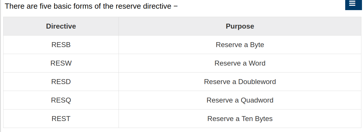
Multiple Initializations The TIMES directive allows multiple initializations to the same value. For example, an array named marks of size 9 can be defined and initialized to zero using the following statement −
marks TIMES 9 DW 0
Immediate addressing mode
mov A,#23H ; #23H real value
accumilator ??
Direct addressing
mov A,23H ; 23 addess value moves to A

mov 23H,33H ; 33 addess value moves to adress 23


mov 26H,#33H ; 33 value moves to address 26
Register Addessing
you can assign those variables with binary or hexadecimal values. Binary values would need to be appended by the letter ‘b’ at the end of the number. Likewise, hexadecimals with ‘h’ at the end. If the hexadecimal numbers start with letters (i.e. A, B, C, D, E, or F), you need to add a zero in front of that number and add an ‘h’ after that number.
bits  db 101001b
var2  dw 4567h
var3  dw 0BABEh
Similarly, you can load the variables to a register or store them back. You can even transfer values between registers.
mov bx, [our_var]
mov cx, bx
mov [our_var], cx
Note the square brackets when you deal with variables. these square brackets are good to distinguish the variable from its address
There are caveats in using mov command. You CANNOT use mov [var1], [var2]. In other words, mov command cannot transfer values between two variables directly
So, how can we get around with this? Use the register.
Suppose both var1 and var2 are word variables. We can use any word registers (AX, BX, CX, DX, and so on) to do the transfer. Suppose we use AX. Thus, mov [var1], [var2] must be transformed into:
mov ax, [var2] mov [var1],ax
The assembler actually treat variables as a label that has an address in the memory (RAM in most cases) associated to it.
mov will read and write 2 bytes instead of 1. Likewise, using byte register to move a word variable will only transfer one byte instead of two.
 var2 db 2
   var3 dw 305h

start:
   mov ax, [var1]  ; ax now equals to 0201h (i.e. 2*256+1)
   mov ax, [var3]  ; ax now equals to 0305h
   mov ax, [var2]  ; ax now equals to 0502h
   mov al, [var3]  ; al now equals to 05h
MOV EAX,myvar2
The EAX register is now a pointer to myvar2. It does not contain the contents of myvar2 (which may not even be a double word), but it contains the address of myvar2.
Variables as Pointers
Once we have moved an address into a 32 bit register, we are then free to move it into a double word variable for storage.
For example, suppose that EAX has been loaded with the address of some memory location storing a byte of data and suppose that we have a double word variable mypoint, say, that we want to store this address in. We simply write
MOV [mypoint],EAX
Now here comes the tricky part. Let’s suppose we want to load the contents of the memory location now pointed to by mypoint, into the CH register. Firstly we have to retrieve the address from storage:
MOV EBX,[mypoint]
Now EBX points to the location in question. Now to retrieve the byte of data at that location, we write
MOV CH,[EBX]
Here the square brackets do not denote the contents of EBX itself (for which we would just write EBX), but rather, they denote the contents of the location pointed to by EBX.
Although this usage of the square brackets may seem different to the earlier usage, it is in reality the same thing, since the thing inside the brackets is basically a pointer in both cases.
EAX used to be called the accumulator since it was used by a number of arithmetic operations, and ECX was known as the counter since it was used to hold a loop index. Whereas most of the registers have lost their special purposes in the modern instruction set, by convention, two are reserved for special purposes — the stack pointer (ESP) and the base pointer (EBP).
.DATA
var	DB 64  		; Declare a byte, referred to as location var, containing the value 64.
var2	DB ?	; Declare an uninitialized byte, referred to as location var2.
DB 10			; Declare a byte with no label, containing the value 10. Its location is var2 + 1.
X	DW ?		; Declare a 2-byte uninitialized value, referred to as location X.
Y	DD 30000    ; Declare a 4-byte value, referred to as location Y, initialized to 30000.
C pointer
#include <stdio.h>
int main () {

   int  var = 20;   /* actual variable declaration */
   int  *ip;        /* pointer variable declaration */

   ip = &var;  /* store address of var in pointer variable*/

   printf("Address of var variable: %x\n", &var  );

   /* address stored in pointer variable */
   printf("Address stored in ip variable: %x\n", ip );

   /* access the value using the pointer */
   printf("Value of *ip variable: %d\n", *ip );

   return 0;
}
assebmly        | c language
----------------|------------
mov eax,ebx 	| eax  = ebx
mov eax,[ebx] 	| eax  = *ebx
mov [eax],ebx 	| *eax = ebx
mov eax,[myvar] | eax  = myvar
mov eax,myvar 	| eax  = &myvar
assembly number differnces decimal or hex or ansi??
Numerical data is generally represented in binary system. Arithmetic instructions operate on binary data. When numbers are displayed on screen or entered from keyboard, they are in ASCII form.
proc_name: procedure body … ret The procedure is called from another function by using the CALL instruction. The CALL instruction should have the name of the called procedure as an argument as shown below −
CALL proc_name
The C, C++, C#, Java, and other C-derivative programming languages use the prefix “0x” to denote a hexadecimal value. Therefore, you’d use the character sequence “0xdead” for the hexadecimal value DEAD16
So for hexadecimal values that don’t already begin with a numeric digit, you would add “0” to the beginning of the value (adding a zero to the beginning of any numeric representation does not alter the value of that representation). For example, use “0deadh” to unambiguously represent the hexadecimal value DEAD
101.01 The conversion to decimal yields: 1 × 2^2 + 1 × 2^0 + 1 × 2^-2 = 4 + 1 + 0.25 = 5.25
Tags: assembly Previous Post: JavaScript basic Next Post: Arithmetic Series